
Progressing Cavity Pump Selection Guide: How to Choose a PCP for an Oil Well
· By Diego Cordova, President
How to select a progressing cavity pump for an oil well: displacement, lift rating, elastomer, rods, torque anchor and drive head, plus a quick chooser.
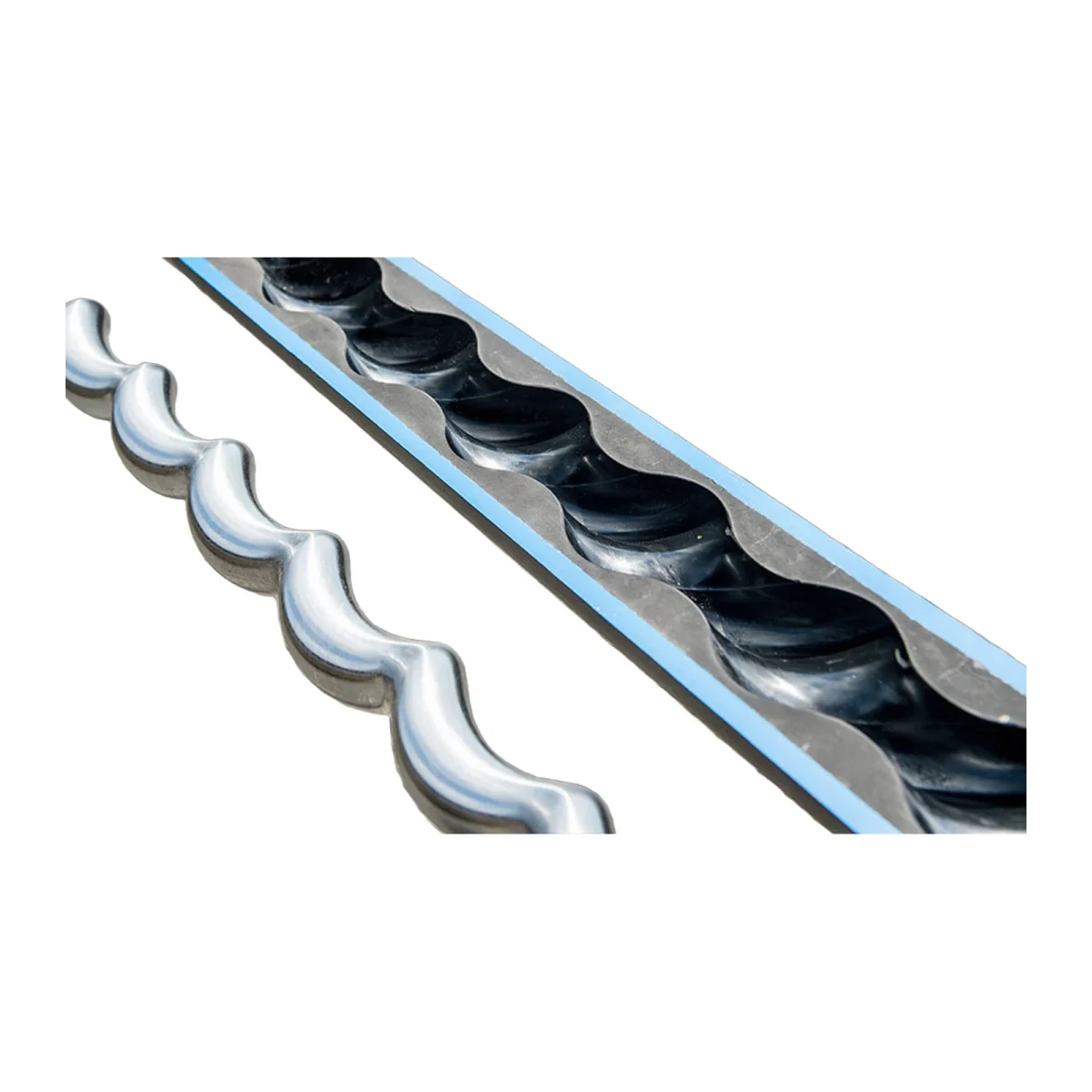
A progressing cavity pump (PCP) is selected in a fixed order: first the displacement that delivers your target rate at a sensible speed, then a lift rating that covers the real pressure across the pump, then an elastomer that survives your crude, gas and temperature, and finally the rod string, torque anchor and wellhead drive that carry the torque from surface to rotor. Get the elastomer or the torque path wrong and even a correctly sized pump will fail early. This guide walks through each decision, with the formulas, a comparison table and a quick chooser at the end.
How a downhole PCP works
A downhole PCP has two main parts: a single helical steel rotor connected to the rod string, and a double helical, elastomer lined stator attached to the tubing string. As the rotor turns inside the stator it forms sealed cavities that move fluid upward continuously. There are no valves to clog or gas lock, and flow is proportional to speed, which is why PCPs are common in heavy oil, sandy wells and coal seam gas dewatering.
Design, testing and performance rating of downhole PCPs are covered by ISO 15136-1 (Pumps). Surface drive systems are covered by ISO 15136-2. Note that ISO 15136-1 explicitly excludes tag bars, gas separators and torque anchors, so those components need their own specification.
For context on where PCPs sit against rod pumps and other methods, see our overview of artificial lift systems.
Step 1: read the pump designation
Manufacturers name PCPs by displacement and lift, but the units differ. Two examples from official catalogs:
| Manufacturer convention | Example | What the numbers mean |
|---|---|---|
| Displacement per 100 rpm, nominal lift (metric) | 15-1400 | 15 m³/day per 100 rpm, 1,400 m nominal lift |
| Imperial equivalent | 13-6000 | 13 bbl/day per 100 rpm, 6,000 ft (same pump as metric 2-1800) |
| Displacement per rpm, head | Model tables list m³/d/rpm and head in m | e.g. 0.03 m³/d/rpm, 610 m head |
Always confirm which basis a datasheet uses before comparing two quotes. A pump listed "per rpm" and one listed "per 100 rpm" differ by a factor of 100 on paper.
Step 2: size the displacement
Required displacement comes from the target rate, the planned speed and the volumetric efficiency you expect:
Displacement per 100 rpm = target rate ÷ (rpm ÷ 100 × volumetric efficiency)
Worked example (illustrative only): a well that should make 30 m³/day, run at 250 rpm, with an assumed 80% volumetric efficiency, needs 30 ÷ (2.5 × 0.8) = 15 m³/day per 100 rpm. The real efficiency at your lift and viscosity must come from the manufacturer's performance curve, not from this example.
Practical rule: choose the displacement so the normal operating speed sits in the middle of the drive's range. That leaves room to speed up as the well declines or water cut changes, without starting at the top of the curve where rod torque and stator wear are highest.
Step 3: check the lift rating
The pump must hold the differential pressure between its intake and its discharge:
Net pressure across pump = tubing head pressure + hydrostatic pressure of the fluid column + flow friction − pump intake pressure
Compare that number with the nominal lift rating. Ratings are published in metres or feet and in pressure units; in one major catalog, for example, a 1,000 m rating is listed as 9,653 kPa (1,400 psi). Running a pump above its rated pressure per stage increases slip and heats the elastomer, which shortens stator life. Keep a margin between the calculated net pressure and the nominal rating, and recheck it if wellhead pressure or fluid density changes.
Step 4: choose the elastomer
The elastomer is the part most often blamed for short runs, and it is the one decision that cannot be made from a table alone. Both major manufacturers state that final selection should be confirmed with swell or bond validation tests on the actual reservoir fluid.
| Elastomer family | Strength stated by manufacturer | Typical use |
|---|---|---|
| Nitrile (NBR), high ACN | Most versatile general purpose compound | Medium and heavy oil, moderate temperature |
| Soft nitrile (NBR) | High abrasion resistance, handles solids | Sandy wells, varying water cut |
| Hydrogenated nitrile (HNBR) | Higher temperature (150 °C stated by one manufacturer), H2S and CO2 resistance | Hot wells, sour service, thermal operations |
| Fluorocarbon (FKM) | Best performer for higher aromatics | Light oil and condensate where nitriles swell |
Key variables to give your supplier: API gravity, aromatics content, H2S and CO2 partial pressures, bottomhole temperature, water cut and sand content. Warranty terms in at least one official catalog exclude failures from incompatibility between produced fluid and the stator, which tells you how much weight this step carries.
Step 5: tubing pump or insertable pump
In a conventional (tubing) PCP the stator is run on the tubing and the rotor on the rods, so changing the stator means pulling tubing. Insertable designs are run inside the tubing on the rod string, which can reduce workover time on wells that need frequent pump changes, at the cost of smaller displacement for a given tubing size. Your casing and tubing size set the maximum stator OD, so confirm drift against the manufacturer's family table.
Step 6: rod string, torque anchor and drive head
A PCP turns the whole rod string, so the torque path matters as much as the pump:
- Rods: check that the rod string carries the combined pump torque, friction torque and axial load. In deviated wells, centralizing couplings reduce rod on tubing wear.
- Torque anchor: the stator reaction torque tends to back off the tubing. A torque anchor below the pump holds the tubing string against that rotation.
- Tag bar (stop bushing): sets the rotor space out at the bottom of the stator.
- Wellhead drive: must cover polished rod speed, torque and thrust load, and include a backspin brake. When the drive stops, the stored torque in the rods and the fluid column above the pump spin the string backwards, so braking capacity is a safety item, not an option.
- Variable speed drive: lets you adjust rate by speed and track torque, which is often the first sign of a stator or pump off problem.
As a reference point, Energinn's direct drive wellhead drive is rated to 500 RPM, with continuous torque of 1,950 ft-lb (single motor, up to 125 HP) or 3,000 ft-lb (dual motor, 150 HP), brake torque of 3,105 ft-lb and a hydraulic backspin brake that generates no sparks.
Free gas and sand
Free gas occupies cavity volume and lowers volumetric efficiency; it also heats the elastomer because gas does not carry heat away like liquid. Setting the intake below the perforations helps, and a downhole gas separator below the pump removes free gas before it reaches the intake. Our helical separator has no moving parts and is rated up to 90% separation efficiency for casing from 4 in to 9-5/8 in.
Sand is handled well by PCPs compared with valve based pumps, but sand still wears the rotor coating and the stator. Soft nitrile compounds, hard chrome rotors and slotted tag bars are the usual responses.
Practical field insights
- Size for the middle of the speed range. A pump that only meets target at maximum speed has no room for decline and runs at peak wear from day one.
- Run a swell test with your own crude. Two wells with the same API gravity can attack the same elastomer very differently because of aromatics and gas composition.
- Never skip the torque anchor. Backed off tubing is an expensive and avoidable failure.
- Treat backspin as a safety hazard. Confirm brake capacity against the maximum torque the string can store before the first start.
- Watch torque, not only flow. A rising torque trend at constant speed usually points to stator swelling or solids; a sudden torque drop often means the pump is running dry.
- Keep the drive head serviced. Gear oil level and seal condition on the drive are routine checks that prevent unplanned shutdowns.
Quick chooser
| Your situation | Start with |
|---|---|
| Heavy oil, moderate temperature, little gas | Conventional PCP, nitrile elastomer |
| Sandy production | Soft nitrile, slotted tag bar, review rotor coating |
| Hot well or sour service | HNBR elastomer, confirm with swell test |
| Light oil or condensate with high aromatics | FKM elastomer |
| High gas to liquid ratio | Gas separator below the pump, intake below perforations |
| Frequent pump changes expected | Insertable PCP if displacement allows |
| Low rate, shallow well | Small displacement pump, check minimum stable speed |
FAQ
What does a PCP designation like 15-1400 mean?
In the metric convention used by one major manufacturer, 15 is the displacement in m³/day per 100 rpm and 1,400 is the nominal lift in metres. Other manufacturers publish displacement per rpm, so always check the datasheet basis.
How fast should a downhole PCP run?
Speed is limited by the pump, the rods and the drive. Size the pump so normal operation sits in the middle of the drive's speed range rather than at its maximum, and confirm rod and drive torque at that speed.
Which elastomer is best for an oil well?
There is no single best compound. Nitrile is the general purpose choice, HNBR covers higher temperature and sour service, and FKM handles high aromatics. Confirm with a swell test on your reservoir fluid.
Why does a PCP need a torque anchor?
The stator reacts against the turning rotor and tends to unscrew the tubing. A torque anchor holds the tubing string in place so the connections do not back off.
What standard applies to PCP systems?
ISO 15136-1 covers downhole pumps and ISO 15136-2 covers surface drive systems. Tag bars, gas separators and torque anchors are outside the scope of ISO 15136-1.
Equipment for your PCP system
Energinn supplies the complete PCP string: progressing cavity pumps by flow range, low rate pumps of 1.6 and 3 m³/d, direct drive wellhead drives, variable speed drives for PCP, helical gas separators, torque anchors, sucker rods, centralizing rod couplings, polished rods and rod BOPs. Send us your well data (rate, depth, fluid properties, casing and tubing) and we will help you match pump, elastomer and drive. Shipping terms are DAP.
For more on lift technology trends, read Field proven innovations in artificial lift.