
Tubing Encapsulated Cable (TEC) in Oil & Gas: Types, Applications, and Best Practices
· By Diego Cordova
What tubing encapsulated cable is, how it is built, the common types and materials, where it is used downhole, and the best practices for selecting and installing it.
Introduction
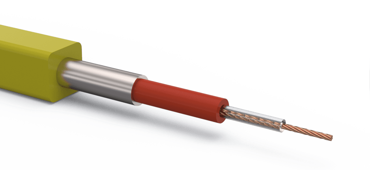
In modern oil and gas operations, data and power need to travel reliably from the surface to downhole equipment under extremely harsh conditions. Tubing Encapsulated Cable (TEC) has emerged as a critical technology to meet this challenge. Tubing Encapsulated Cable (TEC) refers to a specially constructed cable designed to withstand the high pressures, temperatures, and corrosive fluids found inside oil & gas wells. It typically consists of an insulated conductor or fiber optic line protected by a metal tube, often with an additional polymer jacket for extra durability.
TEC cables enable real-time communication and power delivery to downhole tools such as pressure/temperature sensors, valves, and even certain pump systems. By safeguarding the delicate conductors within a robust outer tubing, TEC cables maintain signal integrity where ordinary cables would fail. This makes them indispensable for permanent downhole monitoring and advanced artificial lift installations. With reservoir pressures declining over a well’s life, operators turn to artificial lift methods and downhole instrumentation to optimize production – and TEC cables are the lifeline that connects those downhole devices to surface systems.
This comprehensive post explores everything about TEC cables: what they are, how they are built, common types and materials, typical uses and applications, and best practices for selection and installation. We will also discuss quality standards in manufacturing, the risks of improper cable selection, and common field issues to avoid. Around the world – from heavy oil fields in Canada to high-gas wells in the United States and smart fields in the Middle East – TEC cables are empowering operators to get critical data from deep underground. Let’s dive into the details of TEC cables and learn how to make the most of this technology.
What is a Tubing Encapsulated Cable (TEC)?
A tubing encapsulated cable, often abbreviated TEC, is a small-diameter downhole cable enclosed in a protective metal tubing. Unlike a standard electrical cable which might have rubber or plastic insulation exposed to the environment, a TEC cable’s conductor (or fiber optic core) is sealed within a continuous metal sheath. This metal encasement is usually made of stainless steel or nickel alloy and serves as a armor against extreme pressures (commonly up to 5,000–10,000 psi or more), high temperatures (often 150°C and above), and corrosive well fluids (like brines or sour gas).
Key characteristics that distinguish TEC cables from regular cables include:
- Pressure Integrity: The metal tube acts as a pressure barrier, allowing the cable to survive in high-pressure zones deep in the well. Even at depths of several thousand feet where pressures are intense, a properly designed TEC maintains its integrity without crushing or fluid ingress.
- Temperature Resistance: TEC cables are built to handle elevated temperatures that would melt or degrade normal cable insulation. Depending on materials, many TEC designs operate in temperatures of 125–177°C (257–350°F) continuously, with specialty designs handling even hotter geothermal conditions.
- Corrosion Protection: The outer tubing (stainless steel or alloy) provides a corrosion-resistant shield. This is crucial in wells containing CO₂, H₂S (hydrogen sulfide), or other corrosive elements that could rapidly deteriorate standard cable jackets.
- Mechanical Strength: The construction gives the cable high tensile strength and crush resistance. TEC cables can be clamped to production tubing and run thousands of feet into a well without snapping under their own weight or getting cut by sharp edges. The metal sheath also prevents rodent damage or abrasion during handling – factors important even beyond oil and gas (such as in mining or subsea telecom cables, where TEC principles are used).
In simpler terms, a TEC cable is built to survive where ordinary cables can’t. They ensure continuous power or data flow in downhole tools like permanent pressure gauges, flow sensors, electric pumps, or fiber-optic monitoring systems. By encapsulating the delicate inner elements from the brutal downhole environment, TEC cables enable reliable long-term service for critical well instrumentation.
Construction and Common Materials of TEC Cables
Designing a TEC cable requires careful selection of materials for each layer of the cable, each serving a specific purpose. A typical tubing encapsulated cable has three primary components: the core (conductor or fiber), the insulation, and the outer encapsulation (metal tubing and optional polymer jacket). Below we break down these components and the common materials used for each:
- Core Conductor or Fiber: The innermost element of a TEC can be an electrical conductor or an optical fiber, depending on its function. For electrical TEC cables, high-conductivity metals are used: Copper is most common (often a copper wire strand or solid wire), sometimes plated with nickel or coated for extra corrosion resistance. Copper provides excellent electrical performance for powering downhole sensors or tools and transmitting sensor signals. In some cases, aluminum conductors are used when weight savings are needed (aluminum is lighter, though less conductive). For data-intensive or sensing applications, the core might be an optical fiber (made of silica glass). Optical fibers in TEC cables carry laser light for communication or distributed sensing and are valued for being immune to electromagnetic interference and capable of high-bandwidth data over long distances.
- Insulation: Surrounding the conductor (if electrical) is an insulation layer, often a high-temperature polymer. Materials like PEEK (Polyether ether ketone), ETFE (ethylene tetrafluoroethylene), or cross-linked polyethylene (XLPE) are commonly used as insulation on the wire to electrically isolate it. This insulation must withstand downhole temperatures without melting or becoming brittle, and also resist chemicals. In fiber-optic TECs, the “insulation” is not electrical but rather protective buffer coatings on the fiber (like polyimide coatings for high temp fibers). Additionally, some TEC designs include a gel or mineral powder filler packed around the core inside the metal tube – this serves to center the conductor/fiber, dampen vibrations, and block any fluids if the tubing ever breaches. A silicone or petroleum-based gel, for instance, can cushion the fiber or wire against shock and also prevent void spaces that could allow water ingress.
- Metal Tubing (Outer Sheath): Encasing everything internally is the key feature of a TEC – a metal tube that runs the length of the cable. This tube is usually made from corrosion-resistant alloys. The most popular choice is Stainless Steel (typically 316L SS) due to its good corrosion resistance in many environments, high strength, and relatively lower cost. For harsher conditions, nickel-based alloys are used; a common one is Incoloy® 825 (Alloy 825) – a nickel-iron-chromium alloy with excellent resistance to sour gas (H₂S) and chlorides. Other materials for the tubing include Monel® 400 or Hastelloy for extremely corrosive environments, or Duplex Stainless Steel which has higher strength (useful if very high tension is expected on the cable). The metal tube can be manufactured in long continuous lengths by welding and drawing processes or by seamless tubing methods, ensuring no weak joints. It’s typically a small diameter tube (on the order of 1/8 inch to 1/4 inch outer diameter, or about 3–6 mm, though larger or smaller sizes exist depending on application). The wall thickness might be ~0.028–0.049 inches (0.7–1.2 mm) to provide a balance of flexibility and strength.
- Polymer Encapsulation (Outer Jacket): Many TEC cables go one step further and add an outer polymer jacket encapsulating the metal tube. This polymer layer (often molded as a round or square profile) acts as a protective cushion and makes handling/installation easier. Polypropylene is a common encapsulation material – it’s a durable plastic that provides impact protection and a degree of thermal insulation for the cable. Polypropylene encapsulation essentially forms a semi-rigid coating around the metal-sheathed cable, preventing metal-on-metal contact when you strap the cable to tubing and helping the cable slide more easily during deployment. Other encapsulation polymers include Polyethylene and PVDF (Polyvinylidene fluoride, known by the trade name Kynar). PVDF has a higher temperature rating than polypropylene and is more resistant to harsh chemicals, making it suitable for hotter wells or those with strong solvents present. The choice of jacket material depends on well conditions: for example, a shallow onshore well at 70°C might use a polypropylene jacketed cable, whereas a 150°C deep well could require a high-temp polymer or even no polymer (bare) to avoid melting. Encapsulation jackets can be extruded in different shapes – round jackets are common for single cables, while square or flat encapsulations are used when combining multiple lines together (to form a “flatpack” that sits neatly against the tubing).
To summarize the materials and their roles, the table below highlights common options:
| Component | Material Options | Purpose & Benefits |
|---|---|---|
| Core (Electrical) | Copper (solid or stranded), often with high-temp insulation (XLPE, PEEK) | Carries power or electrical signals; copper offers excellent conductivity and reliability for downhole gauges and tools. Insulation ensures no shorting and withstands heat. |
| Core (Optical) | Silica Optical Fiber (single-mode or multi-mode), with protective coating | Transmits data as light (for telemetry or sensing). Immune to electrical interference; can provide distributed measurements (temperature, acoustic) along the well. |
| Outer Tubing | 316L Stainless Steel | Standard metal sheath for general downhole conditions; corrosion-resistant in “sweet” wells (no H₂S) and strong enough for high pressure. |
| Incoloy 825 / Alloy 825, Inconel 625, Monel 400 | High nickel alloys for sour service (H₂S present) or high-corrosion environments. Maintain strength and corrosion resistance in extreme conditions, albeit at higher cost. | |
| Duplex or Super Duplex Stainless Steel | Enhanced strength and corrosion resistance; used when higher tensile loads or extra corrosion margin is needed (e.g., deep wells, subsea applications). | |
| Encapsulation Jacket | Polypropylene (PP) | External plastic layer for mechanical protection; improves impact resistance and prevents metal-to-metal contact. Suitable for moderate temperatures (typically up to ~85–100°C). Eases handling during installation. |
| PVDF (Kynar) or Nylon | High-performance jackets for higher temperature operation (PVDF stable to ~130–150°C) and chemical resistance. Provide protection in more extreme wells where PP would soften. | |
| None (Bare Cable) | No polymer jacket; used when smallest OD is required or in very high-temperature wells where polymers would not survive. Relies solely on metal sheath for protection. |
Each material in a TEC cable is chosen to ensure the final cable can operate for years in a tough downhole environment without failure. For example, a downhole pressure gauge in a deep sour gas well might use a cable with an Alloy 825 tube (to resist H₂S), a high-temp insulated copper conductor inside, and perhaps no polymer jacket because the well temperature could exceed the polymer’s limit. On the other hand, a simpler oil well gauge in a mild environment might use a 316L stainless tube and a polypropylene jacket to save cost and add durability during deployment.
Types and Configurations of TEC Cables
TEC cables come in various types and configurations to suit different well applications. Key variations include the number and type of internal conductors, the presence of encapsulation, and multi-line combinations. Below are the most common TEC cable configurations and their typical uses:
- Single-Conductor vs. Multi-Conductor TEC: Many standard TEC cables used for downhole sensors have a single electrical conductor inside (single-core). This is often sufficient to power and read a simple pressure/temperature gauge (using the well’s tubing as the return ground path). However, some advanced tools or redundancy requirements call for multi-conductor TEC cables, which can have two, three or even more conductors bundled within one tubing. A three-conductor TEC, for instance, might be used for more complex downhole instruments or for certain electrical submersible pump (ESP) sensor lines that require three-phase power or separate signal lines. Multi-conductor TECs naturally have a larger diameter to accommodate additional wires and insulation, and they may be slightly stiffer. The choice depends on tool requirements: a digital gauge that communicates via a protocol might only need one conductor, whereas an analog sensor could need a separate power and signal return, etc. Importantly, each conductor in a multi-core TEC is insulated from the others, and the whole bundle is encased in the single metal tube. For fiber-optic TECs, you could similarly have multi-fiber cables (with multiple fibers in one tube) if you need various sensor lines (for example, one fiber for distributed temperature sensing and another for acoustic sensing).
- Bare vs. Encapsulated TEC: As noted, bare TEC cable refers to the cable with just the metal outer tubing and no added polymer jacket. Encapsulated TEC cable has an additional plastic coating molded around it. Both types have their place. A bare TEC is smaller in profile – advantageous in tight completions or when running through narrow clamps and wellhead feed-throughs. Bare cables also avoid any polymer exposure to heat, so they can handle higher temperatures. On the downside, a bare cable is more exposed to mechanical damage during handling and can vibrate or rub directly on metal tubing or casing. Encapsulated TEC, in contrast, is more robust against physical damage. The encapsulation (often polypropylene) acts like a bumper, absorbing clamping forces and impacts. It also provides a consistent outer shape (commonly a round cross-section about 3/8 inch or ~9–11 mm in diameter, or a square profile of similar size) which can be easier to secure with cable clamps. The polymer layer also helps space the cable slightly off the tubing, protecting it from being pinched. However, encapsulated cables are bulkier and the polymer has temperature limits. Many operators choose encapsulated designs for deviated or horizontal wells (where the cable might press against the wellbore) and keep bare designs for vertical, high-temp, or space-constrained jobs. Energinn has extensive experience manufacturing TEC cables in both forms – from traditional bare tubing-encapsulated cable designs to polypropylene-encapsulated cables – to suit different operational needs.
- Hybrid and Composite Cables: Some TEC cables are designed to incorporate multiple elements in one package. For instance, a hybrid TEC might include both an electrical conductor and a fiber optic strand within the same tubing, providing power and optical data in one cable. These hybrid cables enable, for example, powering a downhole gauge electrically while simultaneously carrying a fiber for distributed temperature sensing – particularly useful in advanced well monitoring setups. Another form of combination is not within one tube but as a bundled assembly: multiple parallel lines (TEC cables, sensor lines, injection capillary tubes, etc.) can be encapsulated together in a flatpack. A flatpack is essentially a flat, ribbon-like bundle where, say, a TEC cable and a chemical injection line are bound side by side by an outer polymer jacket. This makes installing multiple services along the tubing more efficient (only one string to clamp instead of several loose lines). Commonly, flatpacks might combine an ESP power cable, a TEC sensor cable, and maybe a control line for safety valve, all in one neat bundle for running in a well. The encapsulation keeps them organized and protected. The configuration of TEC (round vs flat, single vs multiple) is chosen based on the well completion design and what equipment needs to be deployed. Table below summarizes a few typical TEC cable styles and use-cases:
| TEC Cable Style | Description | Typical Use Cases |
|---|---|---|
| Single-Conductor Bare TEC | One copper conductor in a metal tube, no outer polymer. Slim profile, high-temp capable. | Permanent downhole gauges in high-temperature wells or wells with minimal clearance. Common for basic pressure/temperature sensors where robustness is key and space is tight. |
| Multi-Conductor TEC | Two or more conductors within one metal tube (usually slightly larger diameter). May be bare or encapsulated. | Advanced sensors or multi-drop gauge systems requiring separate lines (e.g., pressure and temperature separate, or redundant gauges). Also used for certain electric downhole tools needing multiple feed-through wires. |
| Fiber-Optic TEC | One or more optical fibers inside a metal tube, with or without polymer jacket. | Distributed sensing (DTS for temperature along the wellbore, DAS for acoustic/vibration monitoring) and high-speed data transmission. Often deployed in smart wells or for reservoir surveillance. |
| Polymer-Encapsulated TEC | A metal-sheathed TEC cable with an outer plastic jacket (round or square cross-section). | Deviated or horizontal wells where cable needs extra protection; high-vibration installations; general use where handling damage is a concern. Easier to clamp on tubing due to uniform shape. |
| Flatpack (Composite Bundle) | Multiple parallel lines (could be TEC + control line, or multiple TEC cables) encapsulated together in a flat profile. | Complex completions with various downhole devices. For example, wells with an ESP pump (power cable) plus a monitoring TEC line and a chemical injection line all run together neatly. Simplifies installation in offshore or deviated wells by consolidating lines. |
As shown, TEC cables can be tailored to the technical demands of the well. Whether it’s a simple single-conductor cable to monitor a pump intake pressure, or a sophisticated bundle with fiber optics for reservoir surveillance, the modular nature of TEC design allows engineers to mix and match components. It’s important to consult with cable experts and consider the well parameters (pressure, temperature, fluids, device requirements) when selecting the type of TEC cable for a job. In the next section, we’ll look at where these cables are actually put to use in the oilfield and why they are so crucial.
Applications of TEC Cables in Oil & Gas
TEC cables are predominantly used in the oil and gas industry, especially in downhole (subsurface) applications where continuous monitoring or tool control is needed. Below are some of the primary applications of tubing encapsulated cables in oil & gas wells, along with examples of how they add value in the field:
Permanent Downhole Sensors with Progressing Cavity Pumps (PCP)
One major application of TEC cables is in wells that use Progressing Cavity Pumps (PCPs) for artificial lift, particularly heavy oil wells. PCP systems (which often involve a helical rotor/stator pump driven by a rotating rod string from surface) benefit greatly from permanent downhole gauges installed near the pump intake. These gauges (typically measuring pressure and temperature) are connected to surface via a TEC cable strapped along the production tubing. In heavy oil fields – such as those in Alberta, Canada or in Venezuela – PCPs are common because of their ability to handle viscous fluid and sand. By using a TEC and permanent gauge, operators can monitor bottom-hole pressure and temperature in real time while the PCP is operating.
Benefits: Real-time data from the downhole sensor allows for optimized pump speed and performance. For example, if the pump intake pressure drops too low (indicating the pump is drawing more fluid than the reservoir can deliver), the operator can slow the PCP to avoid “pump-off” or excessive gas entrainment. Conversely, rising intake pressure might signal a flow restriction or a need to speed up the pump. The TEC-fed sensor essentially serves as the pump’s “eyes and ears” downhole, enabling proactive adjustments. It also helps in early detection of issues like gas locking, sanding up, or declining reservoir pressure. With continuous downhole readings, operators can fine-tune the PCP and avoid costly interventions.
Why TEC is needed: PCP wells can be deep (several thousand feet) and often deviated, with high chances of gas and solids production. A regular cable would not survive being run along the tubing in such conditions; the TEC’s metal sheath protects the gauge line from the torque and movement of the rod string and from abrasion if the tubing contacts the casing. Moreover, the heavy oil environment can be hot and chemically aggressive – conditions where the TEC’s robust construction is vital. In summary, TEC cables enable permanent monitoring in PCP-lifted wells, which improves the efficiency and reliability of heavy oil production.
Gas Lift Completions – Downhole Monitoring
Gas Lift is another widely-used artificial lift method, especially in high gas-oil ratio wells and deep wells (commonly seen in the United States, the Middle East, and offshore platforms worldwide). In gas lift, compressed gas is injected down the casing-tubing annulus and enters the production stream through valves, lightening the hydrostatic column and helping lift fluids. While gas lift is a relatively simple and robust system, optimizing it for maximum production is a challenge – it requires balancing injection rates, valve performance, and reservoir response. This is where TEC cables with downhole sensors come into play.
Operators often install permanent downhole pressure gauges in gas lift wells to monitor the flowing bottomhole pressure or tubing intake pressure in real time. The gauge might be positioned at a strategic point, such as below the lowest gas injection valve or in the tubing tail, to accurately measure how effectively the lift gas is reducing fluid density. The TEC cable provides the pathway to power this downhole gauge (if it’s an electronic sensor) and transmit the pressure/temperature data to surface continuously.
In the United States, many mature fields (like parts of Texas and Oklahoma) use gas lift and have embraced real-time downhole monitoring to fine-tune gas injection. By analyzing downhole pressure trends, engineers can adjust gas injection rates on the fly, achieving better production rates and avoiding instability. For instance, a problem called “heading” (cyclic surging flow) in gas lift wells can often be diagnosed and mitigated by looking at the downhole pressure fluctuations – data only available thanks to TEC-line gauges. Furthermore, if a gas lift valve malfunctions or the injected gas isn’t reaching as deep as intended, the downhole sensor will reveal an unexpected pressure profile, prompting timely intervention.
TEC cable advantages in gas lift: Gas lift wells can be very deep (often >10,000 feet) and have high pressures at depth; the TEC cable’s strength and pressure rating are essential for survival. Also, gas lift involves continuous gas flow which can cause temperature changes and even vibration in the well – TEC cables are constructed to handle these dynamic conditions without fatiguing. In the field, it’s common to see gas lift wells with multiple TEC cables: one for the permanent gauge and sometimes additional ones if multiple sensing points are installed. These cables are typically clamped to the tubing alongside the gas lift mandrels, and run up to a wellhead outlet where they connect to surface readout equipment. The result is a smart gas lift well that can be remotely monitored and optimized, significantly improving efficiency in places like the Permian Basin (USA) and the Middle East’s giant oil fields.
Emerging Hybrid ESP Applications and Advanced Monitoring
Electric Submersible Pumps (ESPs) are another form of artificial lift, used to achieve very high flow rates by placing an electric centrifugal pump downhole. Traditionally, ESP systems have their own power cable (a heavy-duty 3-phase cable) to run the motor, and they often include a basic downhole sensor package for temperature and pressure near the pump. However, new hybrid applications and advanced monitoring techniques are pushing the integration of TEC cables with ESP systems in innovative ways.
One emerging approach is the Hybrid ESP-Gas Lift system. In some deep or high-volume wells, operators combine an ESP with gas lift injection to improve reliability and flexibility. For example, gas lift might be used to kick off production or to assist an ESP during periods of high gas volume fraction that would normally cause the pump to gas lock. In such hybrid setups, TEC cables can be used to monitor pressures at multiple points (such as above and below the ESP, or in the annulus) to coordinate the two lift methods. The real-time data ensures that the gas injection complements the ESP operation rather than hinders it. If the ESP is shut down for maintenance, gas lift alone can keep the well flowing, guided by the downhole pressure data from the TEC-line sensors. This hybrid strategy has been piloted in some fields to reduce ESP downtime and extend run life, by preventing the pump from operating outside its optimal range.
Another special application gaining traction is the use of fiber-optic TEC cables in ESP wells to gather a wealth of diagnostic information. Fiber-optic TEC lines can be installed alongside the ESP’s power cable (or even integrated into the cable bundle) to perform Distributed Temperature Sensing (DTS) and Distributed Acoustic Sensing (DAS) along the production tubing. With DTS, operators get a continuous temperature profile of the well, which can identify issues like fluid entry points, gas breakout, or scaling in near-real-time. DAS uses the fiber to act as an array of microphones listening to acoustic vibrations: it can detect phenomena such as sand production (by the sound of sand impingement), ESP pump cavitation noise, or even the sound of gas entering a gas lift valve. These techniques elevate ESP monitoring far beyond the traditional single-point sensor, moving towards a fully “instrumented wellbore.”
Implementing such fiber-optic monitoring requires robust TEC cables to protect the delicate fibers in the harsh ESP environment. The TEC cable might be strapped along with the ESP power cable and must endure the same conditions: high temperature (many ESPs operate in 120–150°C wells), high vibration from the pump, and significant pressure. Success in this area means earlier warning of ESP problems and the ability to optimize performance remotely, reducing the costly workovers typically associated with ESP failures.
Summary of special ESP applications: Whether it’s a hybrid ESP with supplementary gas lift or an ESP with fiber-optic sensing, TEC cables are the enabling infrastructure that makes these advanced configurations possible. They provide the physical link for sensors and fibers that deliver data to the surface. These applications are relatively new but spreading, particularly in high-value wells (offshore platforms, deepwater projects, and technologically advanced onshore fields in the USA and Middle East). As digital oilfield initiatives expand, we can expect to see more ESPs deployed with additional TEC cable lines for comprehensive downhole monitoring and even control – truly merging artificial lift with smart well technology.
Manufacturing and Quality Assurance of TEC Cables
TEC cables must be manufactured to exacting standards, given that a failure downhole can mean lost data or even loss of a well’s integrity. The manufacturing process for tubing encapsulated cables is a blend of electrical cable production and high-precision tubing fabrication, followed by rigorous testing. Here’s an overview of how TEC cables are made and the quality controls involved:
1. Core Preparation: The process starts with the preparation of the core element – this could be a spool of insulated copper wire or a reel of optical fiber. If it’s a multi-conductor design, multiple wires are arranged in parallel or twisted configuration as needed. The insulation on electrical cores is applied (by extrusion or wrapping) to the conductor to the specified thickness. For fiber optic cores, manufacturers often apply buffer coatings or place the fiber in a tiny plastic loose tube for protection. The core is usually wound onto a payoff spool, ready to be inserted into the metal tubing.
2. Tubing Encapsulation (Sheathing): Next comes the critical step of encasing the core in metal. There are a couple of techniques:
- Welded & Drawn Tubing: A flat strip of metal (stainless steel or alloy) is formed into a tube around the core and then longitudinally welded to seal it. This welded tube is subsequently drawn through a series of dies to reduce diameter and wall thickness to the final size, effectively shrinking the tube tightly around the core and improving weld integrity. This process produces a continuous, hermetically sealed metal sheath around the cable core.
- Seamless Tubing Feed: In some cases, pre-made seamless tubing is used. The tubing (initially slightly larger ID than the core) is fed over the core and pulled, sometimes with the aid of a vacuum or a mandrel, and then reduced. This method avoids a weld but can be limited in length or more complex for long continuous lengths.
During this stage, precision is key to ensure no gaps or flaws in the metal sheath. The metal tube provides the cable’s strength and pressure seal, so manufacturers use techniques like X-ray or ultrasonic inspection of the weld seam and dimensional checks during drawing to maintain quality.
3. Adding Filler (if required): For certain designs, after the tube is sealed around the core, a filler material is added. Some TEC cables have an inner filler like magnesium oxide powder (common in mineral insulated cables) or a silicone gel injected to fill any voids. This filler helps in two ways: it provides extra insulation and prevents the core from moving or rattling inside the tube (which could cause wear over time). Not all TEC cables have filler – some rely on a snug fit of the insulation and tube – but for high-vibration environments or fiber optic TECs, fillers are quite beneficial.
4. Polymer Encapsulation (Jacket Extrusion): If the design calls for an outer polymer jacket (encapsulated TEC), the next step is to run the metal-sheathed cable through a polymer extrusion line. Similar to how electrical cables get a plastic coating, the TEC is passed through an extruder that applies molten polymer (e.g., polypropylene or PVDF) around it. The extrusion die can be shaped to produce a round cable or a flat profile encasing multiple lines side-by-side. The polymer adheres and cools onto the metal cable, forming a tough outer layer. This process must be carefully controlled to get consistent thickness and to avoid exposing the cable to temperatures that could damage the inner insulation or the core itself. For example, polypro jackets are often extruded at a few millimeters thickness around the tube. In multi-line flatpacks, this step encapsulates all lines together. After extrusion, the jacketed cable is cooled (often through a water trough) and wound onto large spools.
5. Spooling and Handling: TEC cables are produced in continuous lengths which can be several thousand meters long (depending on well depth requirements). The finished cable is spooled onto large reels. Proper tension and layering are important to avoid any kinks or crushing of the cable on the reel. Manufacturers take care to spool the cable with a minimum bend radius respected, as bending too tightly could deform the metal tubing or fiber inside. Often, a protective wrapping is added on the spool to keep the cable clean and prevent any physical damage during transport.
6. Testing & Quality Assurance: Before a TEC cable batch is certified for use, it undergoes a battery of quality tests:
- Pressure Testing: Samples of the cable (or sometimes full lengths) are pressure-tested in a chamber to ensure the metal sheath has no leaks. For instance, a cable rated to 10,000 psi might be tested at 12,000 psi external pressure to verify it won’t collapse or allow fluid intrusion. This simulates the downhole pressure conditions.
- Tensile Strength Testing: Cables are tested for how much pulling force they can withstand. This is important because during installation the cable will experience tension from its own weight and the act of pulling it into the well. Engineers calculate the expected deployment tension and ensure the cable’s tested breaking strength is well above that.
- Electrical Tests: For electrical TEC cables, continuity and insulation resistance tests are performed. A megohmmeter (megger) test applies a high DC voltage between the conductor and the outer sheath to ensure there are no insulation breakdowns (the reading should be an extremely high resistance, indicating no leaks). The conductor is also tested for resistance along its length to ensure it meets specifications (which correlates to the quality of the copper and the cross-sectional area).
- Optical Tests: For fiber optic cores, an optical time-domain reflectometer (OTDR) test is done to check the fiber’s integrity and losses over length. Any microbends or breaks in the fiber introduced during manufacturing would show up as high loss events, so this test ensures the fiber is continuous and performing within acceptable attenuation levels.
- Dimensional and Visual Checks: The cable’s outside diameter is measured at various points to make sure it’s consistent (especially important for fitting through packoffs and clamps). The surface of the cable (and jacket, if present) is inspected for any defects, scratches, or eccentricities.
- Compliance & Certification: Reputable TEC cable manufacturers follow industry quality systems like API Q1 or ISO 9001 for their processes. Material traceability (e.g., ensuring the metal tubing is of the specified alloy and heat treatment) is documented. In certain cases, specific industry standards or client specifications must be met – for example, a cable destined for a sour gas well might need to comply with NACE MR0175/ISO 15156 (material requirements for H₂S environments) in its metallurgy.
Quality assurance is crucial because once the cable is installed there is no easy fix if it fails. A downhole cable failure might mean losing a valuable sensor or even requiring a costly workover to replace the cable. Thus, manufacturers typically ship TEC cables with detailed test certificates and handling guidelines. Field technicians also sometimes do a quick retest (like a pressure test on a small sample, or an electrical continuity check) on location before running the cable, as a final verification.
Modern advances in manufacturing (like laser welding, improved extrusion techniques, and automated testing) have continuously improved the reliability of TEC cables. Companies like Energinn leverage these technologies and stringent QA/QC processes to provide high-quality TEC cables that meet the demanding standards of the oilfield. Every reel of our TEC cable is delivered with confidence that it has been proven fit for service in the toughest conditions.
Risks of Improper Selection and Common Field Problems
Selecting the right TEC cable for a well is not just a matter of ordering any cable – using the wrong type or mishandling the cable can lead to serious problems. In this section, we outline the risks associated with poor TEC cable selection and highlight common issues that can occur in the field, along with ways to mitigate them.
Risks of Choosing the Wrong TEC Cable:
- Inadequate Temperature/Pressure Rating: If a cable not rated for the well’s temperature or pressure is used, it can fail prematurely. For instance, using a polypropylene-encapsulated TEC in a well that hits 130°C will likely result in the outer jacket softening or melting. This can expose the metal sheath to damage or cause the insulation to degrade, eventually shorting out the conductor. Similarly, a cable with a thin wall meant for 5,000 psi service might collapse or burst in a 10,000 psi well. The result is loss of communication with the downhole tool (at best) or a stuck cable/string (at worst). It’s essential to match the cable’s spec (temperature, pressure) with the well conditions plus a safety margin.
- Material Compatibility Issues: Not all wells have the same chemistry. A sour well (with H₂S) requires corrosion-resistant alloy tubing (like Incoloy 825 or Monel). If one were to mistakenly use a 316 stainless steel sheathed TEC in a high-H₂S environment, there’s a risk of stress-corrosion cracking or pitting of the tube over time. This could let well fluids seep into the cable, shorting the wire or ruining a fiber, often irreparably. Likewise, if a well has high CO₂ or chloride content, material selection must account for those to prevent corrosion. Always consider the well’s fluid composition (H₂S, CO₂, chlorides, water salinity) when selecting the tubing material and any exposed metal parts of the cable system.
- Improper Size or Type: The physical size and configuration of the TEC must fit the completion. Using a cable that’s too large in diameter for the available space in clamps or through pack-off seals can cause installation headaches. On the flip side, choosing an extremely small diameter cable (for easier fit) could mean it has lower mechanical strength; in a deep well, the cable might snap under its own weight or during a hard pull. Also, consider flexibility – a rigid large OD cable may not bend smoothly inside a deviated well, whereas a more flexible smaller cable would. Each well may have specific constraints (like a narrow tubing-casing annulus clearance, or tight-radius wellbore curvatures), so the cable must be sized appropriately.
- Insufficient Conductors or Incompatible Tool: There have been instances where a cable was run only to find out it doesn’t electrically interface correctly with the sensor (e.g., a gauge needing two conductors but only a one-conductor cable was provided, or an analog sensor used with a cable that had too high resistance over the length). To avoid this, ensure the cable’s electrical specifications (conductor count, wire gauge, resistance, etc.) match the downhole device’s requirements. Using the wrong type can mean starting over with a costly replacement.
Common Field Installation Problems and How to Avoid Them:
- Cable Damage During Run-In: One of the most common issues is physical damage to the TEC cable as the completion is run into the well. This can happen if clamping practices are not followed – e.g., if clamps (the devices that attach the cable to the tubing) are spaced too far apart, the cable can bow out and potentially get pinched against the casing or snag on a collar. If clamps are over-tightened or have sharp edges, they might even crush or cut into the cable (especially for bare cables without a cushioning jacket). To mitigate these risks, it’s important to use proper cable protector clamps at recommended intervals (often every 20-30 ft, and closer in deviated sections). These clamps should be designed for TEC cables, with smooth grooves and appropriate sizing. Running the assembly in hole should be done carefully; any sudden stops or jarring can whip the cable. Field crews often monitor cable tension as they run in – too much drag could indicate the cable is hung up somewhere.
- Poor Splices or Connections: TEC cables usually need to be spliced either when attaching the downhole gauge (connecting the short pigtail from the gauge to the main cable) or when joining two lengths of cable. A splice is a critical point that must maintain electrical continuity and seal against well fluids. In the field, technicians use special TEC splice kits to perform this operation. A splice kit typically includes a smaller tube or coupling that connects the two cable ends, along with new insulation material, sealants, and sometimes a secondary protective sleeve. If a splice is done improperly – for example, if the crimping of the conductors is loose, or the sealing epoxy isn’t cured fully – it can become the weakest link. A bad splice might introduce high resistance or an intermittent signal (causing faulty readings), and it could allow water ingress that eventually shorts the line. It’s crucial to follow the manufacturer’s procedure for splicing: cleaning the cable ends, using the correct crimping tools, curing any sealant for the recommended time, and verifying the splice by testing (pressure and continuity) before deploying further. High-quality TEC splice kit assemblies are designed to withstand downhole conditions (often rated to the same pressure as the cable, e.g., 10k psi). Always insist on using the proper kit – a DIY or ad-hoc splice job is a recipe for failure.
- Wellhead Penetration Issues: Bringing the TEC cable out of the well at surface requires a wellhead outlet (feed-through) that maintains the pressure seal of the well. This is a specialized device that mounts on the wellhead (often on the tubing hanger or a side port) and seals around the cable while providing an electrical feed-through connector or fiber feed-through. A common problem is trying to jury-rig a feed-through if the correct one isn’t on hand, or damaging the cable while installing the feed-through packoff. An improper seal here can lead to pressure leaks at the wellhead, posing safety hazards. Thus, selecting the correct TEC wellhead outlet that matches the cable size and is rated for the well pressure is essential. When installing, follow the procedure (which often includes stripping a portion of the outer jacket, if any, and securing the cable in a gland or penetrator assembly). Ensure any O-rings or sealing elements are in place and that the cable isn’t kinked through the outlet. A wellhead outlet not only prevents leaks but also protects the delicate transition of the cable from the pressurized well environment to the surface connection. Skipping this device or using an ill-fitting one can result in a dangerous situation or water ingress into the cable from the top.
- Abrasion and Wear Over Time: In wells with significant deviation or where the tubing might move (like thermal wells that expand/contract or injectors that experience frack hits), the TEC cable can rub against the casing or other equipment. Over years, this abrasion could wear through a polymer encapsulation and eventually even the metal sheath. That’s why encapsulated cables or protective cable guards are recommended in such scenarios. Field operations should also plan the cable routing and clamp placement to minimize any section where the cable might be slack and able to rub. Regular well surveillance via the data itself can help – for example, a slowly increasing noise in the signal or intermittent failures might indicate cable damage developing, prompting an investigation or preemptive workover.
Mitigation and Best Practices: To summarize, avoiding TEC cable problems comes down to proper planning and strict adherence to best practices:
- Select the appropriate cable type and materials for the well conditions (consult with experts or manufacturers if unsure).
- Use proper accessory equipment: the right splice kits, the correct wellhead outlets, and good cable clamps/protectors throughout the well.
- Have experienced technicians handle the installation – small mistakes during make-up (like nicking the cable while cutting off excess length, or not tightening a splice fitting fully) can have big consequences later.
- Test continuity and insulation at multiple stages: before running (to have a baseline), after any splices, after the cable is installed but before final hookup, etc. This way, if something goes wrong, you catch it before the well is closed up.
- Keep detailed records of the cable used (batch numbers, test results) and the installation conditions. If a failure does occur, this helps in troubleshooting and working with the manufacturer on root cause analysis.
By taking these precautions, operators can greatly increase the likelihood that their TEC cable will perform flawlessly for the life of the well. Remember that a TEC cable, while robust, is still a lifeline – treat it with care and it will reward you with reliable data and operation. Companies like Energinn not only supply the cables themselves but also provide the supporting tools (from splice kits to wellhead outlets) and expertise to ensure a smooth deployment in the field.
Conclusion
Tubing Encapsulated Cables have become a backbone of modern well completions, enabling everything from permanent reservoir monitoring to sophisticated artificial lift controls. By providing a durable, sealed pathway for power and data, TEC cables allow oil and gas operators to gain invaluable insight into downhole conditions and operate tools at depths and environments that would otherwise be impossible. In this post, we covered what TEC cables are and how they are constructed using specialized materials to endure extreme pressures, temperatures, and corrosive fluids. We also explored the various types of TEC cables – whether bare or encapsulated, single or multi-conductor, electrical or fiber optic – and how each finds its niche in the industry.
Crucially, we looked at real-world applications: from improving heavy oil PCP operations in Canada with permanent gauges, to optimizing gas lift wells in the USA with downhole pressure data, to emerging hybrid ESP installations that marry high production with high-tech monitoring. In all these cases, TEC cables are the enabling technology that deliver real-time data and reliable power to downhole equipment, ultimately increasing efficiency, safety, and production in oilfield operations.
Quality manufacturing and proper selection of TEC cables cannot be overstated. A well-made cable that adheres to strict quality standards (pressure tested, strength tested, and certified) will perform under the harshest conditions – but it must also be the right cable for the job. Using the correct materials and design for each well’s conditions, and handling the cable correctly during installation, are paramount to success. We highlighted common pitfalls like wrong material choices or poor splicing, which can jeopardize an entire project. By being aware of these issues and following best practices (with the help of appropriate accessories and expert guidance), operators can avoid failures and ensure their downhole cables have a long service life.
As the industry continues toward more automated and data-driven operations, TEC cables are likely to play an even bigger role in the future. New sensor technologies, more widespread use of fiber optics for reservoir surveillance, and smart completion designs all rely on robust downhole cabling solutions. Innovations such as high-temperature superconducting cables for deep geothermal wells or hybrid electro-fiber cables for real-time pump monitoring are on the horizon, expanding the capabilities of what a TEC cable can do.
Energinn is proud to be at the forefront of this field, with experience in designing and manufacturing a range of tubing-encapsulated cables and related completion hardware. Whether it’s a standard bare TEC cable or a custom encapsulated assembly, we focus on quality and reliability to meet the demands of each specific application. With the right TEC cable in place, operators can trust that their downhole sensors and tools will stay connected and operational, delivering the data and performance needed to make informed decisions and keep production flowing.
In conclusion, TEC cables might be behind-the-scenes components, but their impact on oil and gas operations is enormous. From maximizing production and protecting expensive equipment, to enabling new technologies like smart wells and real-time analytics, TEC cables truly tie the digital thread through the oilfield’s physical world. As you plan your next well completion or artificial lift installation, give the humble TEC cable the attention it deserves – it just might be the difference-maker in your project’s success.